Демо-лицензия – как попробовать и как купить?
Если вас заинтересовала эта программа, рекомендуем, не откладывая в долгий ящик, заказать демо-лицензию нового релиза CAM350, написав официальному реселлеру на info@pcbsoft.ru и указав название и веб-сайт вашей компании и МАК-адрес вашего компьютера. Вы сможете на практике убедиться, насколько эта программа облегчает жизнь разработчиков печатных плат, и мы надеемся, что применение CAM350 поднимет эффективность и прибыльность ваших разработок на новый уровень, недостижимый для ваших конкурентов.
Отметим, что CAM350 V14.0 поддерживает как локальные, так и сетевые бесконечные лицензии, с ежегодной оплатой доступа к обновлениям. Стоимость лицензии вполне бюджетна и начинается от 2000 USD (за вариант «только для просмотра»).
Gerber Viewer by CircuitPeople
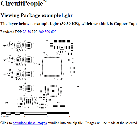
Gerber Viewer by CircuitPeople is the last website in my list to view Gerber files. However, only allows you to view only one file at a time in a fixed view. This website actually does not provide a viewer to render the GBR file. But this website using a different approach to show you the circuit design. After uploading the Gerber file on this website it will show different views of the file from a different perspective. You can analyze the design and you can also export it as a PNG image.
This website is a bit old and extremely simple to show GBR file to you. Just go to the homepage of the website and then upload the Gerber file from your PC. After that, it will show you the circuit design. You can analyze the circuit designs that it shows and eventually export it as an image. The option to export it as an image is at the bottom of the website.
Final Words
DaredevilThese are the best free online Gerber viewer websites that I have found. You can use all the website I have mentioned easily to view Gerber files. What I like about some of these websites is their ability to import multiple GBR files to view them. So, if you are looking for some free online Gerber viewer websites, then this list will surely come in handy. You just have to upload single or multiple GBR files and view them in any way you like.
Online Gerber Files Viewer by PCBWay:
You can also use the Cadsoft Eagle software for viewing the Gerber files, but I recommend you should use the PCBWay Online Gerber Viewer.
Let’s check our generated PCB Gerber files using the PCBWay Online Gerber viewer.
Search for the PCBWay online Gerber viewer.
Click on the PCBWay online Gerber viewer link.
Simply drag and drop the zip folder that we just created. Or you can use the + button to add the zip folder. The time you add the zip folder, all the files are loaded. Click on the top to check the top side of the PCB.
On the bottom to check the bottom side of the PCB.
Click on the layers to check top and bottom sides copper, soldermask, silkscreen, and solderpaste, along with the mechanical stuff. You can easily make any layer visible and invisible by simply clicking on the eye icon next to every layer.
So, this is how easily Gerber files can be generated using the Eagle software. For the step by step procedure watch video given below. Finally, I uploaded the Gerber files on the PCBWay official website.
Generate Fabrication File Gerber
When you finish your PCB, you can output the Fabrication Files(gerber file) via: File > Generate PCB Fabrication File(Gerber) , or Fabrication > PCB Fabrication File(Gerber).
After clicking, will open the Gerber generate dialog:
You can calculate the price for the PCB order, click SAVE to CART will go to JLCPCB and add your PCB in the cart.
Gerber file name
The generated Gerber file is a compressed zip file. After decompression, you can see the following files:
- Gerber_BoardOutline.GKO:PCB Border file. The PCB board factory cuts the shape of the board according to this document. The groove drawn by the EasyEDA, the solid region(Type: NPTH) is reflected in the border file after the Gerber is generated.
- Gerber_TopLayer.GTL:Top side copper layer.
- Gerber_BottomLayer.GBL:Bottom side copper layer.
- Gerber_Inner1.G1,Gerber_Inner2.G1… :Inner copper layer.
- Gerber_TopSilkLayer.GTO:Top silkscreen.
- Gerber_BottomSilkLayer.GBO:Bottom silkscreen.
- Gerber_TopSolderMaskLayer.GTS:Top solder mask. The default board is covered with green oil, and the elements drawn on this layer correspond to the top layer’s area will not be covered with oil.
- Gerber_BottomSolderMaskLayer.GBS:Bottom solder mask. The default board is covered with green oil, and the elements drawn on this layer correspond to the bottom layer’s area will not be covered with oil.
- Gerber_Drill_PTH.DRL:Plated drill through hole layer. This document shows the location of the hole where the inner wall needs to be metallized.
- Gerber_Drill_NPTH.DRL:Non-Plated drill through hole layer. This document shows the location of the hole where the inner wall don’t need to be metallized.
- Gerber_TopPasteMaskLayer.GTP:Top Paste Mask, for the stencil.
- Gerber_BottomPasteMaskLayer.GBP:Bottom Paste Mask, for the stencil.
- ReadOnly.TopAssembly:Top Assembly, read only, doesn’t affect the PCB manufacture.
- ReadOnly.BottomAssembly:Bottom Assembly, read only, doesn’t affect the PCB manufacture.
- ReadOnly.Mechanical:Record the information on the mechanical layer in the PCB design, and only use it for information recording. By default, the shape of the layer is not manufactured at the time of production. Some board manufacturers use the mechanical layer to make the frame when using Altium file to production. When using Gerber file, it is only used for text identification in JLCPCB. For example: process parameters; V cut path etc. In EasyEDA, this layer does not affect the shape of the border of the board.
Notice:
- Before ordering the PCB, please check the gerber at the Gerber view as below.
- The Gerber files are generated by browser, please use the browser inner downloader to download!
- The coordinates of the Gerber file follow the canvas coordinates
- When exporting Gerber, the coordinate format accuracy defaults to 3:3. When the PCB size is out of range, it automatically uses 4:2 format
Build and install instructions
Prerequisites
If you wish to build gerbv from source, your system should have the
following libraries:
- GTK+, the graphical toolkit.
-
Cairo, a graphics library. This
provides advanced graphics rendering capability, as well as Gerber editing.
Building gerbv by downloading a release
- Download source tarballs from here.
- Expand source by running
- Change to newly expanded directory
- Type .
The following (gerbv) switches are available to configure:- : Lists all configure options.
-
: Program will output lots of debug spew while running.
(default = no -> no debug output by default.) -
: Set default unit for coordinates in status bar to mm
(default = no -> units = inches by default.) -
: Link with ElectricFence for malloc debugging
(default = no -> efence off by default.) -
:
Update desktop icon database after installation
(default = no -> desktop icon installed by default.)
- Type
- Type . Please note that if you want to
install it in a system directory you have to first. - Test by typing
Building gerbv by downloading from anonymous git repository
- Check out the source tree:
- Recreate all build system files:
- Type .
The following (gerbv) switches are available to configure:- : Lists all configure options.
-
: Program will output lots of debug spew while running.
(default = no -> no debug output by default.) -
: Set default unit for coordinates in status bar to mm
(default = no -> units = inches by default.) -
: Link with ElectricFence for malloc debugging
(default = no -> efence off by default.) -
:
Update desktop icon database after installation
(default = no -> desktop icon installed by default.)
- Type
- Type . Please note that if you want to
install it in a system directory you have to first. - Test by typing
- Run in the checked out gerbv directory to get the latest changes.
Why do we need to Generate PCB Gerber Files?
Only the PCB board layout file with the extension .brd is not enough to manufacture the PCBs. The PCBs manufacturing companies need the Gerber Files. The Gerber format is an open 2D binary vector image file format. It is the standard file used by printed circuit board (PCB) industry software to describe the printed circuit board images: copper layers, solder mask, legend, etc.
Gerber files should be inside a .rar or.zip archive with standard file extensions:
Extension Layer
pcbname.GTL Top Copper
pcbname.GTS Top Soldermask
pcbname.GTO Top Silkscreen
pcbname.GBL Bottom copper
pcbname.GBS Bottom Soldermask:
pcbname.GBO Bottom Silkscreen:
pcbname.TXT Drills
pcbname.GML/GKO *Board Outline:
Note: 4 layer board also need
pcbname.GL2 Inner Layer2
pcbname.GL3 Inner Layer3
Once the PCB layout is designed you will need to generate the Gerber files. Gerber is used in PCB fabrication data. PCBs are designed on specialized electronic design automation (EDA) or a computer-aided design (CAD) system e.g. Cadsoft Eagle and there are so many other Schematic and PCB designing softwares. The CAD systems output PCB fabrication data to allow fabrication of the PCB board. This data typically contains a Gerber file for each image layer (copper layers, solder mask, legend or silk…). Gerber is also the standard image input format for all bare board fabrication equipment needing image data, such as legend printers, photoplotters, direct imagers or automated optical inspection (AOI) machines and for viewing reference images in different departments. For assembly the fabrication data contains the solder paste layers and the central locations of components to create the stencil and place and bond the components.
Over the last few years there have been several attempts to replace Gerber by formats containing more information than just the layer image, e.g. netlist or component information. None of these attempts have been widely accepted within the electronics manufacturing industry, probably because the formats are complex. Gerber remains the most widely used data transfer format.
Как конвертировать файл GBR
Для преобразования файла необходимо знать, в каком он формате
Это важно для того, чтобы вы знали, какую программу-конвертер использовать, поскольку три упомянутых выше формата не имеют ничего общего друг с другом. Это означает, что вы не можете преобразовать, скажем, файл кисти GIMP в формат файла Gerber; это просто не работает.
Когда дело доходит до преобразования файлов Gerber, вполне возможно, что некоторые из упомянутых выше программ способны не только открывать его, но и сохранять файл GBR в новый формат файла. Если нет, GerbView может конвертировать файлы Gerber в DXF, PDF, DWG, TIFF, SVG и другие форматы файлов.
Онлайн-программа Gerber Viewer может также работать для сохранения файла GBR в формате изображения PNG. FlatCAM может конвертировать файл Gerber в G-код. Вы также можете попробовать Cenon, если другие конвертеры не работают.
Чтобы сохранить файлы GIMP GBR в ABR для использования в Adobe Photoshop, вам сначала нужно преобразовать их в PNG с помощью такой программы, как XnView. Затем откройте файл PNG в Photoshop и выберите, какая часть изображения должна быть превращена в кисть. Проведите кистью через Редактировать > Определить набор настроек кисти меню.
Вы можете конвертировать файлы Game Boy Tileset в другие форматы файлов с помощью упомянутой выше программы Game Boy Tile Designer. Он поддерживает сохранение GBR в Z80, OBJ, C, BIN и S через Отправьте > Экспорт в пункта меню.
The Features of Gerber Viewer
- View, print, mark the conversion of Gerber, Adobe PDF, Excellon and HPGL / 2 raster format.
- Measure the distance, area perimeter, and the pad track which we did not catch.
- Convert multiple Gerber files to a multi-layer PDF, DWF, or DXF file. you can learn more about creating a layered PDF file here.
- Add files by rotating at any angle, and support adding another format file as a layer, and there is no limit to the number of layers, which can be added to the workspace (only in memory).
- The visibility of all loaded files can be set individually.
- Query the information in the Gerber entity, HPGL / 2 Excellon file.
- Support user-defined headers and footers for color or black and white printing. In short, all Windows operating systems can be printed to supported plotter printer devices.
- In the mouse control zoom in, zoom out, zoom in.
- Save the entire workspace or a single file raster file. Supported formats include TIFF, CALS, Adobe PDF, Windows BMP, PNG, JPEG.
- Use lines, text, rectangles, images, QR codes, barcodes, symbols, polygons, and add tags.
FlatCam
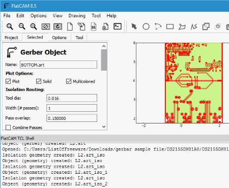
Use FlatCam as a Gerber viewer software or as a Gerber editor to edit PCB board or create one from scratch. It gives you a layer wise view of designs. You can select a component to view its property and also measure distance between two components in mm or inch. It also lets you isolate routing, board cutout, and non-copper region for a detailed view.
A Gerber file opens as project, which can be edited if you want. Add arc, rectangle, polygon, path, and merge polygons. A built-in tool lets you create double sided PCB by inverting layers. It also features a script tool, known as TCL console, which helps users to implement their own features to PCB designs.
Here you can view GRB and G-code files. Designs can be exported as SGV files.
Tracespace Viewer
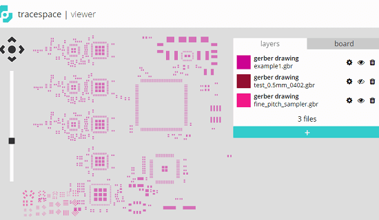
Tracespace Viewer is an open source tool to open and video Gerber files online and analyze them. This website has a very intuitive where you can upload ,multiple GBR files and view them simultaneously as layers. It allows you to turn off or on a layer to see it in the viewer. The viewer of the website supports zoom and pan like features to help you analyze the circuit design. However, this website doesn’t let you export or edit the GBR file. You can only view the GBR file and analyze that.
To view a GBR file on this website, just go to its homepage and then upload the Gerber file. Use the top right section to upload the file using “+” button. You can even upload multiple files and it will list them all. You can then select any layer and it will show in the viewer of the website. After that, you can analyze the design of the circuit and use the tools to assist you or do whatever you want.
Gerbv’s featureset
In summary, gerbv supports the following features:
- Gerbv runs on Linux and other Unices (Linux native).
- An experimental Windows version is available for beta-testing.
- Gerbv displays RS-274X files. (It does not display RS-274D files)
- Gerbv handles aperture macros with up to 10 levels of recursion.
- Gerbv supports complex layer operations (e.g. knockout).
- Gerbv can display many different drill file formats. In particular, Excellon drill
files are supported. Other drill files with similar syntax will also display. - Gerbv displays well-formed pick-and-place files. Pick-place files
should contain XYRS (X, Y, Rotation, placement Side) information, and
be held in a comma-separated ASCII (.csv) format. - Gerbv will autodetect Gerber, drill, or pick-place file type
when reading in the file. - When built using the Cairo
rendering engine, gerbv can display Gerber layers in
«semi-transparent» mode, making it easy to visualize your board’s
stack up. - Gerbv provides facilities for analyzing and validating your Gerber
file’s syntax, code count, aperture usage, etc.
This can be useful in situations in which you are
having problems in the CAM stage of manufacturing your PC Board (i.e.
when your manufacturer is having problems with your files). - When built using Cairo,
gerbv allows for limited Gerber editing. (Currently limited to
object deletion.) - Panning and zooming (both stepwise and outline) of the image is supported.
- Gerbv supports image autoscale — i.e. zoom and pan the image to fit the
viewing window. - Multiple files can be loaded simultaneously and be shown «on top of each
other». - The number of layers you may load simultaneously is unlimited by gerbv.
- The layer order (stackup) may be changed using an intuitive «drag and drop» menu.
- You may turn display of individual layers on and off independently using a checkbox.
- You may set layer colors independently using a pop up color choice window.
- You may change the layer polarity (negative/positive display).
- Gerbv incorporates a measurement tool so you can make measurements on the image.
- Three different measurement units supported: inch, mm, mil (1/1000 inch). Measurement
units are user-selectable - Gerbv can export a layer image to PNG, .ps, .pdf, and .svg, both
from within the GUI as well as via a command line switch (cairo version only). - Gerbv performs negative/scratch draws.
- Gerbv includes a reload operation, which re-reads all loaded files off
disk. This feature is useful when you are manually hacking Gerber files. - Gerbv allows you to save a session into a project file. The project file
stores the names of all loaded files, their stackup, color, etc. so
so you can easily reload all Gerber files in a project at a later date
(e.g. after re-editing then using a PCB layout tool).
Blog Archive
-
►
2020
(1)
►
December
(1)
-
►
2018
(1)
►
January
(1)
-
►
2017
(4)
►
July
(1)
►
May
(1)
►
March
(1)
►
January
(1)
-
►
2016
(10)
►
December
(3)
►
November
(4)
►
May
(1)
►
March
(1)
►
February
(1)
-
►
2015
(7)
►
November
(1)
►
September
(1)
►
August
(1)
►
March
(1)
►
February
(2)
►
January
(1)
-
►
2014
(49)
►
December
(1)
►
November
(2)
►
October
(3)
►
September
(4)
►
August
(3)
►
July
(2)
►
June
(5)
►
May
(5)
►
April
(2)
►
March
(6)
►
February
(9)
►
January
(7)
-
▼
2013
(79)
►
December
(4)
►
November
(10)
-
▼
October
(5)
►
September
(3)
►
August
(7)
►
July
(4)
►
June
(8)
►
May
(9)
►
April
(3)
►
March
(8)
►
February
(8)
►
January
(10)
-
-
►
2012
(74)
►
December
(8)
►
November
(7)
►
October
(3)
►
September
(4)
►
August
(4)
►
July
(4)
►
June
(10)
►
May
(8)
►
April
(8)
►
March
(8)
►
February
(5)
►
January
(5)
-
►
2011
(74)
►
December
(6)
►
November
(7)
►
October
(4)
►
September
(4)
►
August
(2)
►
July
(4)
►
June
(5)
►
May
(6)
►
April
(14)
►
March
(10)
►
February
(7)
►
January
(5)
-
►
2010
(58)
►
December
(5)
►
November
(5)
►
October
(4)
►
September
(5)
►
August
(2)
►
July
(7)
►
June
(2)
►
May
(5)
►
April
(10)
►
March
(5)
►
February
(4)
►
January
(4)
-
►
2009
(43)
►
December
(3)
►
November
(1)
►
October
(2)
►
September
(4)
►
August
(6)
►
July
(9)
►
June
(5)
►
May
(2)
►
April
(2)
►
March
(1)
►
February
(2)
►
January
(6)
-
►
2008
(51)
►
December
(2)
►
October
(1)
►
September
(5)
►
August
(3)
►
July
(3)
►
June
(2)
►
April
(3)
►
March
(13)
►
February
(9)
►
January
(10)
-
►
2007
(11)
►
December
(10)
►
January
(1)
строительство
Каждый файл Gerber всегда содержит только один слой (в техническом выражении «слой»). Если печатная плата состоит из нескольких слоев, например Например, два слоя для отображения электрических соединений в меди, два слоя для паяльной маски и один слой для печати текста на печатной плате, всего для этого требуется пять различных файлов Gerber.
Четыре слоя в формате Гербера
структура
Отдельные элементы (токопроводящие дорожки, контактные площадки и т. Д.) Печатной платы позиционируются с координатами xy. Координаты могут быть указаны в абсолютных или инкрементальных значениях. Единицы могут быть в миллиметрах или дюймах . Координаты даны целыми числами, для более тонких структур необходимо указывать масштабирование. Начальные и конечные нули можно убрать для экономии места для хранения. Основная структура файла Gerber:
Описание формата (абсолютное или инкрементное, без нулей)
Список кодов D
Функция управления и инструмент выбираются с помощью списка кодов D (также известного как таблица диафрагмы). Список кодов D описывает графические инструменты, используемые в файле Gerber (круги, круговые кольца, прямоугольники). Он описывает назначение всех D-кодов в данных Гербера геометрической форме апертуры и механическому размеру апертуры. D1 – D3 — зарезервированные коды; они обозначают не затвор, а включение и выключение источника света фотоплоттера. Есть:
- D1: проведите линию при включенном свете. Предупреждение: это означает не просто «включить свет», а скорее «провести линию», что является важным отличием.
- D2: источник света выключен
- D3: световой импульс ( вспышка )
Проверка Gerber файлов на наличие ошибок — Все начинается с кнопки питания
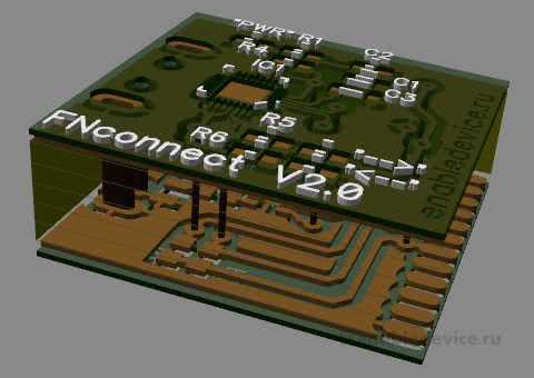
У многих изготовителей плат просмотрщик Gerber файлов есть прямо на сайте, и у нас имеется возможность проверить плату прямо при оформлении заказа. Но так же существуют программы, при помощи которых можно выполнить проверку еще до отправки файлов изготовителю. И сегодня мы рассмотрим оба варианта.
1. ZofzPCB: бесплатный 3D-просмотрщик Gerber файлов.
Для проверки я пользуюсь программой ZofzPCB. На мой взгляд, это просто великолепный 3D-просмотрщик Gerber файлов, который позволяет буквально разобрать плату по слоям и заглянуть внутрь. И при этом, программа полностью бесплатная. Ссылка на программу: https://ru.zofzpcb.com.
Для сборки платы из Gerber файлов переходим в меню «File — Compose New — Manual».
Открываем папку с нужными Gerber файлами, выделяем кликом мыши файл сверловки (fn_adapter.XLN) и помещаем его в соответствующее поле нажатием кнопки «Insert File to Drill Plates».
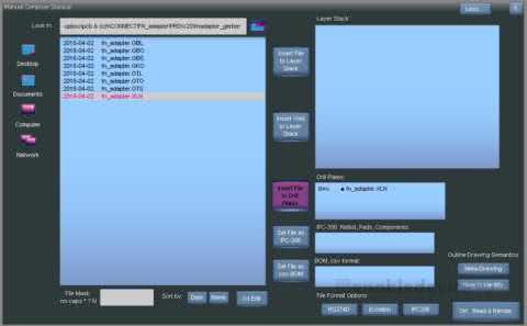
Остальные файлы перемещаем в сте
EasyEDA EasyEDA Gerber Viewer
EasyEDA – бесплатная, не требующая инсталляции облачная система автоматизированного проектирования электроники (EDA). В состав системы входит простой в использовании редактор принципиальных схем, симулятор электронных цепей и система проектирования печатных плат, которые могут быть запущены прямо в вашем браузере. Кроме того, пользователь по завершению разработки печатной платы может заказать ее изготовление прямо из редактора.
Теперь команда разработчиков EasyEDA анонсировала облачный сервис для просмотра Gerber файлов EasyEDA Gerber Viewer, сгенерированных системами проектирования печатных плат, такими как EasyEDA, Eagle, Kicad, Altium, Pads, Diptrace. Инструмент поддерживает работу с Gerber-файлами формата RS-274X, который является промышленным стандартом описания проекта печатной платы для изготовления фотошаблонов на самом разнообразном оборудовании. Пользователь только загружает упакованные в .zip архив Gerber-файлы и система выполняет 2D преобразования для получения высококачественного изображения верхнего и нижнего слоев печатной платы. При этом в фоновом режиме запускается проверка на наличие ошибок разводки и отображается некоторая полезная информация о вашей печатной плате, например, размеры, минимальный зазор между печатными проводниками, минимальная ширина печатных проводников и шелкографии.

Отдельная программа для Gerber файлов – это очень полезный инструмент проверки проекта печатной платы перед отправкой его на изготовление. Здесь можно проверить расположение элементов и отверстий для сверловки, а также корректность экспорта слоя шелкографии в файлы для производства
Доступность такого инструмента в облачном сервисе определяет важное преимущество: вы сможете его использовать в любое время, в любом месте, на любом устройстве, без необходимости устанавливать какое-либо ПО
На данный момент EasyEDA Gerber Viewer доступен только по отдельной ссылке.
Основные преимущества EasyEDA Gerber Viewer:
- Бесплатный облачный сервис для просмотра Gerber-файлов;
- Не требуется установка какого-либо ПО, работа из любого браузера на Windows, MAC, Linux;
- Встроенные функции проверки проекта на наличие ошибок разводки;
- Отображение основных параметров печатной платы, необходимых при заказе на производство;
- Возможность масштабирования изображения и настройки цветовой схемы для слоев;
- Возможность экспорта изображений.
EasyEDA Gerber Viewer имеет простой и понятный пользовательский интерфейс, но несмотря на это предлагается дополнительная справка по работе с системой, а также видеоуроки подготовки Gerber-файлов в различных системах проектирования печатных плат.
Submitting a patch or addition to gerbv
-
We are interested in all ideas and suggestions regarding gerbv. We also
reserve us the right to reject them though. Ideas implemented in source
code always have a greater chance to make it into the release in a near
future. -
If you want to implement something for gerbv there is a certain «code
standard» we try to maintain. That is described in a text file in the
distribution HACKING. Please read it. And check that your code doesn’t
stand out too much from the rest regarding naming of functions and
variables. -
When submitting a patch, the developers prefer git patches. The parameter to use to git is:git format-patch <revision range>
and send us the diff file usingSourceforge’s patch tracker.
-
If you have questions about submitting patches, post them to the
geda-dev mailing list.
Что такое файлы Gerber и Drill
Если вы никогда не изготавливали печатную плату, выражения «файлы Gerber, Excellon и NC Drill» могут показаться совершенно непонятными. В конце концов, разве нельзя просто отправить файлы электрической схемы и проекта печатной платы из приложения для разработки печатной платы изготовителю, и пусть он сам сделает все остальное? Если бы все было так просто. Как все мы знаем, существует множество систем автоматизированного проектирования (САПР) печатных плат. Разные САПР имеют собственные форматы файлов. Представьте только, если бы изготовителю нужно было бы постоянно быть в курсе всех форматов файлов каждого из существующих САПР. Это было бы полное безумие!
Вместо того чтобы использовать собственные форматы файлов систем разработки печатных плат, каждая такая система поддерживает промежуточные производственные файлы, которые называются «Gerber». Эти файлы описывают токопроводящие дорожки каждого слоя печатной платы способом, понятным системе автоматизированного производства (CAM — САП). Разработанные файлы формата Gerber вначале содержали инструкции для фотоплоттера, который создавал изображение печатной платы при помощи света на неэкспонированном листе пленки. В наши дни файлы Gerber используются для управления лазерным плоттером, выполняющим построение изображения всех токопроводящих дорожек, крепежных и переходных отверстий на печатной плате.
Файлы Gerber по типу и формату
Особенность файлов Gerber заключается в том, что каждый сгенерированный вами файл будет связан с определенным слоем проекта печатной платы и будет иметь свое уникальное расширение файла. На сегодняшний день стандартные расширения файлов, с которыми можно работать в САПР/САП, следующие:
Также стоит помнить о том, что есть несколько доступных форматов файлов Gerber – Gerber RS-274D и Gerber RS-274X. Формат D более старый, он использует два файла для описания одного слоя печатной платы. В более новом формат X вся информация из двух файлов объединена в один файл. Что касается управления проектными данными, куда проще следить за одним файлом на слой вместо двух. Мы всегда рекомендуем вам использовать формат Gerber RS-274X. Нет причин в наши дни отказываться от этого формата.
Как насчет сверления отверстий?
Вы могли заметить, что в таблице выше отсутствует кое-что важное – ссылка на файл с отверстиями. На самом деле, это второй файл, который вам необходимо будет отправить изготовителю печатных плат вместе с файлами Gerber
Файл отверстий NC Drill (для станков с числовым программным управлением) будет использоваться для точного определения мест сверления отверстий на печатной плате, а также их размеров. Сразу оговоримся, что вы могли слышать о файле NC Drill, под которым на самом деле подразумевался файл Excellon, предназначенный для сверлильно-трассировочного станка, ранее производимого корпорацией «Excellon».
Теперь, когда у вас есть общее представление о том, что такое файлы Gerber и NC Drill, давайте обратимся к типовой системе проектирования печатных плат и посмотрим, как создавать файлы в этой системе.
Why choose Seeed studio Fusion’s Gerber viewer?
It’s important to check your design before PCB production, take a look at Ben’s review for Fusion Gerber Viewer:
I go this board made at Seeedstudio Fusion The board was really cheap, 4.9$ for 10! The board was finished pretty well for the price and the smaller Via I made had no issues. The vias had a hole size of 20mils and looked clean. The 2 layer board looked similar to others I have made but one massive advantage I found with seeedstudio fusion was the Gerber layer checker online app! I have MCN viewer on OSX and it doesn’t always show the drill hols correctly. This was more of a problem on the headphone driver card ad headphone socket drill holes were not showing up. submitted Gerbers to Fusion and the viewer correctly showed the layers !!!
Unmerical Innovation
A Gerber Viewer and CAM Solution from Numerical innovations. You can download Gerber viewer tools if you always need to check the Gerber files. They offer professorial function and check your Gerber file all round,it is easy to use Gerber Editor, and Panelization, DFM Tool Available, they have a better Gerber Editor with a Modern GUI, also provides DXF/DWG Importer and DFM and Netlist Checker.
You May Also Like
- Basic Knowledge Of Electronic Components
- The Engineer’s Guide To PCB Design
Please follow and like us:
Расширенный Гербер
RS-274X, расширенный Gerber или X-Gerber, был первоначально выпущен в сентябре 1998 года.
Это читаемый человеком формат ASCII . Он состоит из потока команд, генерирующих упорядоченный поток графических объектов. Графические объекты могут быть положительными или отрицательными. Наложенные в правильном порядке, они создают окончательное изображение.
Файл Gerber содержит полное описание изображения слоя печатной платы без использования каких-либо внешних файлов. В нем есть все операторы изображения, необходимые для изображения печатной платы. Можно задать любую форму апертуры. Плоскости и контактные площадки могут быть указаны без как в Standard Gerber. (Однако в некоторых реализациях все еще используется рисование, что проблематично для пользователей этих файлов.)
Выпущенный в феврале 2014 года, Gerber X2 добавляет к изображению дополнительные метаданные. Атрибуты позволяют добавлять метаданные в файл Gerber. Атрибуты похожи на метки, предоставляющие информацию, связанную с файлами изображений или их функциями. Примеры метаданных, передаваемых атрибутами:
- Функция файла. Файл — это верхняя паяльная маска или нижний слой меди и т. Д.?
- Часть, представленная файлом. Представляет ли он отдельную плату, массив или купон?
- Функция прокладки. Является ли вспышка контактной площадкой SMD, переходной площадкой, реперной точкой и т. Д.
Для получения дополнительной информации об атрибутах см. FAQ X2 или вступительное видео по внешним ссылкам.
Производственная документация, такая как отделка, общая толщина и материалы, указывается в отдельном файле задания Gerber.
Пример файла Gerber:
G04 Short version a file taken from the Example Job 1, created by Filip Vermeire, Ucamco*
%TF.FileFunction,Copper,Bot,L4*%
%TF.FilePolarity,Positive*%
%TF.Part,Single*%
%FSLAX36Y36*%
%MOMM*%
%TA.AperFunction,Conductor*%
%ADD10C,0.15000*%
%TA.AperFunction,ViaPad*%
%ADD11C,0.75000*%
%TA.AperFunction,ComponentPad*%
%ADD12C,1.60000*%
%ADD13C,1.70000*%
G01*
G75*
%LPD*%
D10*
X76649990Y36899980D02*
X83949950D01*
X84399990Y37349990D01*
X93699990D01*
D11*
X76649990Y36899985D03*
X83599990Y18749980D03*
X98829985Y36504980D03*
D12*
X460298855Y784148855D03*
D13*
X107299765Y20629885D03*
X109839765D03*
X112379765D03*
M02*
Спецификация формата опубликована на официальном сайте.
Как открыть файлы GBR
Вы можете открывать файлы Gerber с помощью ряда программ, большинство из которых бесплатны. Эти бесплатные зрители Gerber включают GraphiCode GC-Prevue, PentaLogix ViewMate, PTC Creo View Express и Gerbv. Некоторые из них поддерживают печать и просмотр измерений. Вы также можете использовать Altium Designer для открытия файла Gerber, но он не является бесплатным.
Еще один способ просмотра файлов GBR — онлайн. Создатели формата Ucamco имеют бесплатный просмотрщик ссылок Gerber, который позволяет загружать файл GBR онлайн, чтобы просмотреть его в вашем браузере.
Файлы GIMP Brush используются с GIMP, который работает на Windows, MacOS и Linux.
Если ваш файл GBR находится в формате Gameboy Tileset, вы можете открыть его с помощью Gameboy Tile Designer (GBTD).
ViewMate
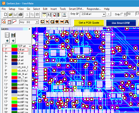
ViewMate is another good free GRB file viewer. It has an extensive list of tools available for enhanced viewing capability. You can use various selection tools to select components, layer options to hide/delete/add layers, visibility toolbar to change layer/component visibility, and do much more. Select a distance unit from inch, mm, mil, and cm to measure distance between components.
Now it lets you add traces/paths to a diagram as orthogonal trace, 90 degrees trace, elbow, circle, add text, etc., but you cannot save the drawing. The drawing with new additions can be however printed.
You can play around with the layers of a Gerber file. It lets you change visibility, change color, and stretch layers. You can also add/remove layers and transfer/replicate/swap layers easily.
Import Gerber files to workspace along with layers, drill and route, and PDF as vector.


